9323 Hamilton
Mentor, Ohio 44060 - USA
Tel:+1-440-357-1400
Fax:+1-440-357-1416
 |
9323 Hamilton Mentor, Ohio 44060 - USA Tel:+1-440-357-1400 Fax:+1-440-357-1416 |
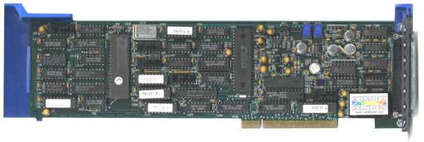
| Product Description | The MC-DAS series of data acquisition products turn
PS/2 Micro Channel computers into a powerful educational, industrial
or scientific workstation. Key data acquisition & control
functions are included in one high performance, low cost package
including: Self calibrating 12 or 16 bit ADC, software programmable
gain amplifiers, five high speed 16 bit timer/counters, digital I/O
and analog-to-digital conversion.

|
 Product Description
Turn your IBM PS/2 MicroChannel or compatible computer into a powerful educational, industrial, or scientific workstation. Key data acquisition & control functions are included in one high performance, low cost package. The self-calibrating, 12-bit analog to digital converter (ADC) handles 16 single-ended or 8 differential input channels at rates up to 100,000 samples/second. Using the Programmable Option Select (POS) technology of the MicroChannel, all analog input features are software configurable.
The precision gain amplifier (software programmable gains of 1, 2, 10, and 100) provides input resolutions between ±100 mV and ±10 Volts. One 12-bit digital to analog converter (DAC) supplies 5mA (2K Ohm load) across either a ±10 Volt or 0 to +10 Volt output range. Five 16-bit precision timer/counters can time intervals to one microsecond or count events to 160 nanosecond resolution. Digital input and output lines (two each) provide access to external devices. A 37-pin D-shell connector interfaces all features to external devices. Completing the system are a 40-pin screw terminal board with RF-shielded cable, the LabPac software package, and utility software.
 Our Solution Includes
 Key Features
 Applications
 Functional Description
The MC-DAS installs internally into an expansion slot of an IBM PS/2
series, MicroChannel computer or compatible. Complete cabling and a screw
terminal board are provided for easy access to all input and output lines. The
MC-DAS fully conforms to the MicroChannel bus specification as an I/O slave,
DMA capable. POS register implementation allows the selection of one of seven
I/O base locations and four interrupt levels.
 Analog-to-Digital Conversion (ADC)
Designed for maximum flexibility, all features of the analog to digital
converter are software configurable. There are no jumpers or switches to
change when resetting the MC-DAS for different input conditions. The analog to
digital converter (ADC) is a 12-bit or 16 bit successive approximation
converter with a 7.5 microsecond conversion time. The software configurable
features of the converter are: Input Type (single-ended or differential),
Input Range (unipolar or bipolar), Channel Select (single or autoscan),
Programmable Gain (1, 2, 10, or 100), ADC trigger, ADC trigger timing, Direct
Memory Access (DMA) conditions (arbitration level and type, Burst Mode, and
non-DMA), and Re-calibration.
The MC-DAS is software configured for 16 single-ended or 8 true differential
input lines. All analog input lines have a 100M Ohm input impedance and are
multiplexed to the ADC. A programmable, precision gain amplifier (1, 2, 10, or
100) at the input to the Sample & Hold circuit allows the input range to
vary from ±100mV to ±10V. The gain of 100 can be modified by a precision
resistor for gains up to 1000. Examples of sensor types that can be used as
analog inputs are: Temperature, Flow, Displacement, Voltage, Current,
Acceleration, Velocity, Level, Pressure, Moisture, and Humidity.
A conversion is started by a software command, a trigger signal from a pacer
clock, a rising edge from an external source, or self-triggered by the end of
the last conversion. Channels can be selected for conversion one at a time or
as a set of consecutive inputs. Software enabled, the auto-scan feature
automatically increments the channel number with each conversion. Both the
starting and ending channel in the sequence are software selectable.
The self-calibration feature of the ADC allows the nulling of internal
conversion errors by resetting the ADC characteristics for the current input
conditions using a software command. Conversion errors due to differential
non-linearity or temperature drift are effectively eliminated because the ADC
will be calibrated for the current environmental state. When going from low to
high gains, the only required hardware adjustment is for the input offset. In
many cases this input offset can be predetermined and subtracted out in
software, freeing the user of all adjustments.
Converted data is transferred to an on-board, 16 sample FIFO buffer. High
speed transfer of the sampled data to a memory buffer is possible using the
Direct Memory Access (DMA) capabilities of the MicroChannel. DMA arbitration
levels, immediate rearbitration, and burst mode transfers are fully supported.
When DMA is used, the end of the conversion strobe will initiate the DMA
request. When not using DMA, the end of a conversion can be detected using an
interrupt or by polling the status register. Data is transferred at the end of
a conversion by reading the converted data byte from the FIFO buffer or via
DMA transfer.
Functional Description - Standard ADC Features
 Digital-to-Analog Conversion (DAC)
The 12-bit digital to analog converter (DAC) has jumper selectable output ranges of ±10 Volts and 0 to +10 Volts. Each output value is latched and remains constant until the next digital value is presented to the DAC. An output buffer generates 5mA of current across the voltage range and permits connection to 2000 Ohm loads. Programming involves writing a 12-bit value to one I/O location.
Functional Description - Standard DAC Features
 System Timer/Counter (STC)
Five independent 16-bit timer/counters count TTL compatible pulses (rising
or falling edge) generated from a wide range of equipment and sensors. Six
separate source and gate input lines are provided on the external connector
for signals that can be used by any counter. A TTL compatible pulse/level
output signal (1 TTL load) is available from three counters.
Each gateable counter can count up or down (binary or binary coded decimal
format) while the accumulated count may be read at any time without disturbing
the counting process. Each of the counters can be connected to others to form
a counter with resolution up to 80 bits. The counters can be driven by an
on-board 1MHz crystal giving them resolutions from 1 microsecond to 10
milliseconds. External events can be counted at speeds to 6.25 MHz.
Programming is accomplished through an 8-bit command register, an 8-bit status
register, and a 16-bit data port. Instructions for direct programming are
contained in the Handbook
Functional Description - Standard Timer/Counter Features
 Digital Input/Output (DIO)
The MC-DAS contains four lines of digital I/O. Two lines are set as inputs and two lines are set as outputs (supply 24mA). The input lines are monitored by reading the value in the MC-DAS Status Register and decoding two bits. The output lines are changed by setting/clearing two bits in a command word and writing the value to the MC-DAS Control Register.
 Interrupts
Hardware interrupts allow the computer's processor to react to special events when they occur. Level sensitive interrupts and interrupt sharing are implemented as required by the MicroChannel bus hardware specification. The MC-DAS provides four software enabled sources for hardware interrupts. The sources are timer/counter output, end of A/D conversion, A/D data overrun, and DMA transfer completed. External signals can be used through the counter source inputs. Software allows any of the interrupt sources on the board to be connected to any of four hardware interrupt request lines (IRQ3, 5, 11, 15). Hardware interrupts require special software called Interrupt Service Routines to process the interrupt.
 Technical Specifications
| MC-DAS 1612 | MC-DAS 1616 | |
| Resolution | 12-bits | 16-bits |
| 0-10V (per interval | 2.44mV/Int | 152µV/Int. |
| ±10V (per interval) | 4.88mV/Int | 304µV/Int. |
| Maximum Throughput | ||
| Gain = 1, 2, or 10 | 100,000/Sec | 40,000/Sec. |
| Gain = 100 | 50,000/Sec | 40,000/Sec. |
| Inherent Quantizing Error | ±l/2 LSB* | ±1/2 LSB* |
| Linearity | ±l/2 LSB* | ±1/2 LSB* |
| Differential Linearity | ±l/2 LSB* | ±1/2 LSB* |
| Monotonicity | 0º to 70ºC | 0º to 70ºC |
| Temp. Coef. of Linearity | 1.0 ppm/ºC | 0.14 ppm/ºC |
| Temp. Coef of Diff. Lin | 0.2 ppm/ºC | 0.2 ppm/ºC |
| Temp. Coef. of Offset | 0.4 ppm/ºC | 0.2 ppm/ºC |
| Power Supply Rejection @ 1KHz | >= 8OdB | >= 8OdB |
| * Maximum over full temperature range (0º to 70ºC) |
| MC-DAS 1612 | MC-DAS 1616 | |
| Maximum Input Voltage (No damage) | ||
| Power OFF | +10 Volts | +10 Volts |
| Power ON | +25 Volts | +25 Volts |
| Normal Input Range | +10 Volts | +10 Volts |
| Input Resistance | 1012Ohms | 1012Ohms |
| Source Impedance | <10 KOhms | <10 KOhms |
| Dif. Amp. CMRR (Gain=1,60Hz) | 89 dB | 89 dB |
| Gain Linearity (%FSR) | ||
| Gain = 1, 2, or 10 | 0.001% | 0.001% |
| Gain = 100 | 0.006% | 0.005% |
| Temp. Coef. of Gain Linearity | l0ppm/ºc | l0ppm/ºC |
| MC-DAS 1612 | MC-DAS 1616 | |
| Sample/Hold Aperture Uncertainty | 0.3 Nanosec | 0.3 Nanosec |
| Sample/Hold Feedthrough | -80 dB | -80 dB |
| System Accuracy (%FSR) | ||
| Gain = 1 or 2 | 0.0020% | 0.0030% |
| Gain = 10 | 0.0025% | 0.0040% |
| Gain = 100 | 0.0030% | 0.0050% |
| Operating Temperature | 0º to 70º Celsius |
| Storage Temperature | -25º to +85º Celsius |
| Hardware Interrupts | IRQ 3, 5, 11, 15 |
| Power: +5 Volts | 1700 mA typical |
| +12 Volts | 72 mA typical |
| -12 Volts | 39 mA typical |
| Load | 1 TTL load/bus line maximum |
| DMA | Full arbitration & Burst Mode |
| Slots | One slot in PS/2 |
| Address | 8 consecutive I/O word locations |
| Agency Approvals | FCC-A (Business & Industry), CE-Mark, UL Label |
System Accuracy
The analog to digital conversion system of the MC-DAS 1612 consists of the
analog input multiplexers, the precision gain amplifier, the sample &
hold, and the ADC. Each of the parts of the system have individual accuracy
specs. System accuracy, however, is the precision of the signal when it is
processed through all of the parts. An accuracy spec can only be determined by
testing complete systems. Comprehensive tests of the MC-DAS 1612 indicate its
system accuracy is 12 bits ±1/10 LSB. This means the full 12-bit resolution of
the ADC is accurately delivered.
Tests of the MC-DAS 1616 indicate its system accuracy is 14 bits. For any 100
samples, 70% will be accurate to 16 bits, with the remaining samples falling
within a normal distribution around the correct value. The main factor
decreasing the system accuracy is wideband noise inside the ADC. Noise in the
digital domain can be reduced by sampling at higher rates and averaging
multiple samples. Over sampling spreads the ADC noise over a wider band.
Averaging applies a low-pass response which filters noise above the desired
signal bandwidth. Depending on the waveform under analysis, there are
different digital low-pass filters that can be applied. All major statistical
and analytical packages contain filter algorithms to apply to raw data.
| Operating Temperature | 0º to 70º Celsius |
| Storage Temperature | -25º to +85º Celsius |
| Relative Humidity | To 95% non-condensing |
| Agency Approvals | Class A, CE-Mark |
Specifications subject to change without notice.
Scientific Solutions liability, trademarks, and export notices apply.
Copyright © 1974-2014 Scientific Solutions - All rights reserved