
9323 Hamilton
Mentor, Ohio 44060 - USA
Tel:+1-440-357-1400
Fax:+1-440-357-1416
 |
9323 Hamilton Mentor, Ohio 44060 - USA Tel:+1-440-357-1400 Fax:+1-440-357-1416 |
Digital I/O signals from the computer are typically TTL type of signals. This means that they are 5v logic and can typically source/sink current in the 15 to 64ma range. If you need to control or sense higher voltage signals (example 60v DC or 120v/240v AC) and/or higher current signals (example 3 Amps instead of 64ma), then a solution could be to use Solid-State-Relays (SSR).
Our Solid State Relays are implemented as pluggable modules that can be installed into a "Solid State Relay Rack". The SSR modules provide a convenient method for interfacing real world signals to the computer interface. The modules come in 4 flavors (which are also made in different colors to help distinguish them)
The OUTPUT modules are used to switch AC or DC loads such as lights, motors, solenoids. The 5v logic signal from the computer controls the SSR, which in turn switches the DC/AC load ON or OFF. The INPUT modules are used to "sense" AC or DC loads - meaning that they are used to monitor the Loads to determine when an AC or DC signal is present. All of the modules have optical isolation circuits that provide a 4000 volt optically isolated barrier between the computer electronics and the Load devices that are being controlled.
The Modules also come in two different sizes: Standard or Mini. The Standard size was the first size introduced a number of years ago. The Mini size is a physically smaller version (saves 35% space). The use of the Mini size allows you to have more Modules in a smaller area. The Relay Racks for the Mini are much smaller than they are for the Standard as discussed later in this document.
Standard Module Dimensions: 1.70" long x 1.25" high x 0.60" wide (43.2mm x 31.8mm x 15.2mm)
Mini Module Dimensions: 1.70" long x 1.00" high x 0.40" wide (43.2mm x 25.4mm x 10.2mm)
The AC OUTPUT modules have zero-crossing detection circuitry that
ensure that the AC signal is only switched ON or OFF during the zero
volt crossing of the AC signal. This is desirable as it greatly
reduces generated Electrical Magnetic Interference (EMI) and Radio
Frequency Interference (RFI) that are sources of noise. These modules
are also highly immune to electrical transients and have built in RC
snubber networks for increased capability with inductive loads.
Non-zero crossing modules are also available as an option for those
applications that would rather have the EMI/RFI effects but have faster
switching times
The DC OUTPUT modules can operate DC loads over a wide voltage range
(typically 3 Vdc to 60 Vdc or 200 Vdc) and have built in
spike protection. The 60 Vdc versions are the most common and
offer the faster switching times and handle a larger electrical current.
The INPUT modules are used to monitor the status of and AC or DC
loads. For example, you would use these type of modules to determine if
a voltage is present such as from a temperature or pressure switch,
limit
switch or switch toggled manually.
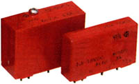
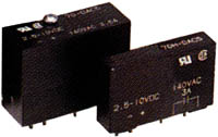
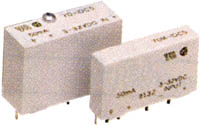
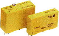
The following tables show a picture of both the "Standard" and
"Mini" Modules in addition to providing a summary of the specifications.
DC OUTPUTODC5(RED Color)
|
 |
||
| Part Number |
0381006
(standard) 0381010 (mini) |
0381017
(standard) 0381021 (mini) |
|
| Normal State |
Normally OPEN |
Normally OPEN |
|
| SPECIFICATION |
UNITS | ||
| Maximum Load Voltage |
Vdc |
60 |
200 |
| Load Voltage Range |
Vdc |
3 to 60 |
4 to 200 |
| On State Voltage Drop (maximum) |
Vdc |
1.20 |
1.75 |
| Load Current Range @ 25 deg C |
Amp |
0.02 to 3.0 |
0.02 to 1.0 |
| Surge Current maximum for 1
second |
Amp |
5 |
5 |
| Power Dissipation |
Watt/Amp |
1.0 |
1.5 |
| Max. Off-state Leakage @60Vdc |
mA |
1.5 |
0.010 |
| Maximum Turn-on Time |
usec |
20 |
75 |
| Maximum Turn-off Time |
usec |
50 |
750 |
| Nominal Logic Voltage |
Vdc |
5 |
5 |
| Max. Logic Supply Current @
Nominal VCC |
mA |
14 | 18 |
| Logic Input Resistance Rx |
Ohm |
300 | 220 |
| Minimum Drop Out Voltage |
Vdc |
1 |
1 |
| Clamping Voltage (maximum) |
Vdc |
80 |
360 |
| Transient Power Dissipation |
400 Watts at
1mS (non-Recurring) |
400 Watts at
1mS (non-Recurring) |
|
| Insulation Resistance (Input to
Output; Input or Output to Case) |
MOhm |
10,000 |
10,000 |
| Dielectric Strength Input to
Output (minimum) |
Vac (rms) |
4000 |
4000 |
| Input to Output Capacitance
(typical) |
pF |
10 |
10 |
| Vibration 10-2000Hz per
MIL-STD-202, Method 204, Condition D. |
20 G's peak
or 0.06" double amplitude |
20 G's peak
or 0.06" double amplitude |
|
| Mechanical Shock per
MIL-STD-202, Method 213, Condition F. |
1500 G's
0.5mS half-sine |
1500 G's
0.5mS half-sine |
|
| Storage Temperature |
-40 C to
+125 C |
||
| Operating Temperature |
-40 C to
+100 C |
||
AC OUTPUTOAC5(BLACK Color)
|
 |
||
| Part Number |
0381005
(standard) 0381009 (mini) |
0381016
(standard) 0381020 (mini) |
|
| Normal State |
Normally OPEN Zero-Crossing Turn-On |
Normally OPEN Zero-Crossing Turn-On |
|
| SPECIFICATION |
UNITS | ||
| Nominal Load Voltage | Vac |
120 |
240 |
| Load Voltage Range |
Vac |
24-140 |
24-280 |
| On State Voltage Drop (peak) |
Volts,max |
1.5 |
1.5 |
| Frequency Range |
Hz |
25 to 70 |
25 to 70 |
| Minimum Peak Blocking Voltage | Volts | 400 | 600 |
| Load Current Range @ 25 deg C |
Amp, rms |
0.03 to 3.0 |
0.03 to 3.0 |
| Max Surge Current (peak) Do not repeat until module temp returns to steady-state |
Amp |
80A at
60Hz,1cycle 25A at 60Hz, 60 cycles |
80A at
60Hz,1cycle 25A at 60Hz, 60 cycle |
| Power Dissipation |
Watt/Amp |
1.0 |
1.0 |
| Max. Off-state Leakage @60Hz. |
mA, rms |
2 | 4 |
| Maximum Turn-on Time (60Hz) | mSec |
8.3 | 8.3 |
| Maximum Turn-off Time (60Hz) |
mSec |
8.3 |
8.3 |
| Nominal Logic Voltage |
Vdc |
5 |
5 |
| Max. Logic Supply Current @
Nominal VCC |
mA |
16 | 16 |
| Nominal Logic Input Resistance Rx |
Ohm |
240 | 240 |
| Minimum Drop Out Voltage |
Vdc |
1 |
1 |
| Maximum Zero Voltage Offset |
Vpeak |
8 |
8 |
| Typical Static dV/dT Measured open circuit conditions; not to exceed peak blocking voltage |
3000 volts per mSec | 3000 volts per mSec | |
| Load Power Factor (minimum) |
0.4 |
0.4 |
|
| Insulation Resistance (Input to
Output; Input or Output to Case) |
MOhm |
10,000 |
10,000 |
| Dielectric Strength Input to
Output (minimum) |
Vac (rms) |
4000 |
4000 |
| Input to Output Capacitance
(typical) |
pF |
6 | 6 |
| Vibration 10-2000Hz per
MIL-STD-202, Method 204, Condition D. |
20 G's peak
or 0.06" double amplitude |
20 G's peak
or 0.06" double amplitude |
|
| Mechanical Shock per
MIL-STD-202, Method 213, Condition F. |
1500 G's
0.5mS half-sine |
1500 G's
0.5mS half-sine |
|
| Storage Temperature |
-40 C to
+125 C |
-40 C to +125 C | |
| Operating Temperature |
-40 C to
+100 C |
40 C to +100 C | |
DC INPUTIDC5(WHITE Color)
|
 |
||
| Part Number |
0381008
(standard) 0381012 (mini) |
0381019
(standard) 0381023 (mini) |
|
| Input Circuit |
Polarized Negative True Logic |
Polarized Negative True Logic |
|
| SPECIFICATION |
UNITS | ||
| Maximum Load Voltage |
Vdc |
32 | 60 |
| Load Voltage Range |
Vdc |
3 to 32 | 35-60 |
| On State Voltage Drop (maximum) |
Vdc |
0.45 Vdc at 50ma | 0.45 Vdc at 50ma |
| Input Current at Max. Input Voltage | mA |
18 |
6 |
| Max. Off-state Leakage Current |
uA |
1.0 |
1.0 |
| Maximum Turn-on Time |
mSec |
0.20 |
10 |
| Maximum Turn-off Time |
mSec |
0.40 |
10 |
| Nominal Logic Voltage |
Vdc |
5 |
5 |
| Max. Logic Supply Current @
Nominal VCC |
mA |
10 | 10 |
| Nominal Input Resistance (Rx) | Ohm |
1.8K | 10K |
| Min. Drop Out Voltage (Output
High) |
Vdc |
1 |
9 |
| Min. Pick Up Voltage (Output Low) |
Vdc |
3 |
35 |
| Output Current Range | mA |
1-50 |
1-50 |
| Insulation Resistance (Input to
Output; Input or Output to Case) |
MOhm |
10,000 |
10,000 |
| Dielectric Strength Input to
Output (minimum) |
Vac (rms) |
4000 |
4000 |
| Vibration 10-2000Hz per
MIL-STD-202, Method 204, Condition D. |
20 G's peak
or 0.06" double amplitude |
20 G's peak
or 0.06" double amplitude |
|
| Mechanical Shock per
MIL-STD-202, Method 213, Condition F. |
1500 G's
0.5mS half-sine |
1500 G's
0.5mS half-sine |
|
| Storage Temperature |
-40 C to
+125 C |
||
| Operating Temperature |
-40 C to
+100 C |
||
AC INPUTIAC5(YELLOW Color)
|
 |
||
| Part Number |
0381007
(standard) 0381011 (mini) |
0381018
(standard) 0381022 (mini) |
|
| Input Circuit | Negative
True Logic |
Negative
True Logic |
|
| SPECIFICATION |
UNITS | ||
| Nominal Load Voltage | Vac |
120 |
240 |
| Load Voltage Range |
Vac |
90-140 |
180-280 |
| On State Voltage Drop | Vdc |
0.45 Vdc at
50mA |
0.45 Vdc at
50mA |
| Input Current at Max Input Voltage | mA, rms |
8 |
6 |
| Max. Off-state Leakage |
uA | 1 |
1 |
| Maximum Turn-on Time | mSec |
20 | 20 |
| Maximum Turn-off Time |
mSec |
20 |
20 |
| Nominal Logic Voltage |
Vdc |
5 |
5 |
| Max. Logic Supply Current @
Nominal VCC |
mA |
10 | 10 |
| Nominal Input Resistance Rx |
Ohm |
22K | 60K |
| Max. Pick Up Voltage (Output Low) | Vac |
90 |
180 |
| Min. Drop Out Voltage (Output
High) |
Vac |
25 | 50 |
| Insulation Resistance (Input to
Output; Input or Output to Case) |
MOhm |
10,000 |
10,000 |
| Dielectric Strength Input to
Output (minimum) |
Vac (rms) |
4000 |
4000 |
| Input to Output Capacitance
(typical) |
pF |
6 | 6 |
| Vibration 10-2000Hz per
MIL-STD-202, Method 204, Condition D. |
20 G's peak
or 0.06" double amplitude |
20 G's peak
or 0.06" double amplitude |
|
| Mechanical Shock per
MIL-STD-202, Method 213, Condition F. |
1500 G's
0.5mS half-sine |
1500 G's
0.5mS half-sine |
|
| Storage Temperature |
-40 C to
+125 C |
-40 C to +125 C | |
| Operating Temperature |
-40 C to
+100 C |
40 C to +100 C | |
Relay Racks are circuit boards that have positions to allow the plugging in of the Digital I/O Modules. The Relay Rack has a connector that allows connection of the Relay Rack to one of Scientific Solutions interface cards such as the BaseBoard/PCI, LabMaster DMA, ADEX, PRO or LabTender. The Relay Rack also has screw terminal "pairs" for each of the modules. These screw terminals are used to connect to your AC or DC load.
Relay Racks come in different sizes to accommodate a different number of Modules. Typical Racks accommodate 8 or 24 Modules. Also, there are different Relay Racks for the Standard versus the Mini size of SSR Modules.
Keep in mind that many times the Digital I/O from the computer is
programmable as INPUT or OUTPUT in 8-bit sections. This means that if
you
have an 8 position Relay Rack, then it will have either all INPUT or
all
OUTPUT type of modules which can be either AC or DC type. So if you
need both INPUT and OUTPUT modules, you would need two 8 position Relay
Racks - or a 24 position Relay Rack where the INPUT and OUTPUT modules
are installed in groups of 8.
The following picture shows a comparison of the Relay Racks:
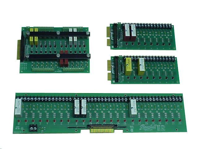
Upper Left: 24 Position Relay Rack for Mini Modules
Upper Right: Two 8 Position Relay Racks for Standard Modules
Bottom: 24 Position
Relay Rack for Standard Modules
Each of the Relay Racks has a 50position header connector which is
used with a ribbon cable to connect to the appropriate connector on the
Scientific Solutions product, i.e. BaseBoard PCI, LabMaster DMA,
etc. The Solid State Relay Modules plug into the racks as shown
in the picture. Associated with each module is two screw
terminals that are used to connect to your AC or DC load. Note
that in the picture the same type of module (INPUT or OUTPUT) is used
for each 8-position section. This means that an 8position rack
can use all INPUT or OUPUT, but cannot mix. So if you need to use
INPUT and OUPUT modules simultaneously you would need at least two of
the 8-position racks or a rack with more positions such as a 24
position version.
The Relay Racks and Solid State Modules are normally used with
Scientific Solutions BaseBoard/PCI product. On the front of the
BaseBoard/PCI are four connections, with each connector providing 24
digital I/O signals. Each connection can connect to a single
Relay Rack. So if you wanted to use two of the 8-position racks,
you would use two of the connections on the front of the
BaseBoard/PCI. The 24 position rack would connect to one of the
BaseBoard/PCI front-panel connectors.
| Picture |
Part Number |
Description |
Module Type |
Size |
 |
0381013 |
Relay Rack, 8 Module Position |
Standard | 8" x 3.5" (203.2mm x 88.9mm) |
 |
0381014 |
Relay Rack 24 Module Position |
Standard |
18.75" x 4.5" (476.3mm x 114.3mm) |
 |
0381015 |
Relay Rack 24 Module Position |
Mini |
8" x 6" (203.2mm x 152.4mm) |
Specifications subject to change without notice.
Scientific Solutions liability, trademarks, and export notices apply.
Copyright © 1974-2014 Scientific Solutions - All rights reserved